Overall, the emissions from diesel combustion are far lower than emissions from petrol combustion. shows the comparison between petrol and diesel emissions. The CO, HC, and NOx emissions are lower, mainly due.
Electronic control of diesel injection
The advent of electronic control over the diesel injection pump has allowed many advances over the purely mechanical system. The production of high pressure and injection is, however, still mechanical with all current systems. The following advantages are apparent over the non-electronic control system.
- More precise control of fuel quantity injected..
- Better control of start of injection.
- Idle speed control.
- Control of exhaust gas recirculation.
- Drive-by wire system (potentiometer on throttle pedal).
- An anti-surge function.
- Output to data acquisition systems etc.
- Temperature compensation.
- Cruise control.
Fuel pressure is applied to a roller ring and this controls the start of injection. A solenoid-operated valve controls the supply to the roller rink. These actuators together allow control of the start of injection and injection quantity
shows a block diagram of a typical electronic diesel control system. Ideal values for fuel quantity and timing are stored in memory maps in the electronic control unit.
The injected fuel quantity is calculated from the accelerator position and the engine speed. The start of injection is determined by the following:
- Fuel quantity.
- Engine speed.
- Engine temperature.
- Air pressure.
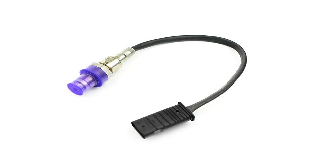
The ECU is able to compare the start of injection with actual delivery from a signal produced by the needle motion sensor in the injector. 40 shows a typical injector complete with a needle motion sensor.
Bosch ‘L’ Jetronic – variations
Owing to continued demands for improvements, the ‘L’ Jetronic system has developed and changed over the years. This section will highlight the main changes that have taken place. The ‘L’ variation is shown
L2-Jetronic
This system is changed little except for the removal of the injector series resistors as the ECU now limits the output current to the injectors. The injector resistance is 16.
LE1-Jetronic
No current resistors are used and the throttle switch is adjustable. The fuel pump does not have safety contacts in the air flow sensor. The safety circuit is incorporated in the electronic relay. This will only allow the fuel pump to operate when an ignition signal is present; that is, when the engine is running or being cranked
LE2-Jetronic
This is very similar to the LE1 systems except for the thermo-time switch and cold start injector are not used. The ECU determines cold starting enrichment and adjusts the injector open period accordingly
The ECU for the L3-Jetronic forms part of the airflow meter installation, as shown in . The ECU now includes a ‘limp home’ facility. The system can be operated with or without lambda closed-loop control. The air-fuel ratio can be adjusted by a screw-operated potentiometer on the side of the ECU.
LH-Jetronic
The LH system incorporates most of the improvements noted above. The main difference is that a hot-wire type of air flow meter is used. The component layout is shown in . Further developments are continuing but, in general, most systems have now developed into combined fuel.
Last word
When the pressure exceeds the pre-set value (of the spring), a valve is opened and the excess fuel returns down a pipe to the tank. The chamber above the diaphragm is connected to the inlet manifold via a pipe.